

Please Leave Us A Message
Privacy statement: Your privacy is very important to Us. Our company promises not to disclose your personal information to any external company with out your explicit permission.
 Huai`an Vanke Hydraulic Machinery Equipment Co.,Ltd
Manually-actuated valve
There are two types of manual directional valves: Spring Reset and Steel Ball OrientaTIon. Figure 5.17 (a) shows a steel ball positioning type three-position four-way manual Directional Valve. After the handle is pushed by hand to move the valve core relative to the valve body, the valve core can be stabilized in three different working positions by the steel ball . Figure 5.17 (b) is a spring-returning three-position four-way manual directional valve. After pushing the spool through the handle, in order to maintain the extreme position, you must hold the handle (Hand Lever) by hand. Once the handle is released, the spool will automatically spring back to the neutral position under the action of the spring force.
5.3.2.2 Mechanically-actuated Valve
Motorized directional valve is also called stroke directional valve. It uses a stopper or cam to push the spool to achieve directional change. Motorized directional valves are mostly two-position valves as shown in Figure 5.18.
Figure 5.17 (c) shows the rotary mobile manual directional valve. The rotary handle can change the working position by pushing the spool through the screw. This structure has the advantages of small size and convenient adjustment. Since the handle of this valve has a lock, it cannot be adjusted without opening the lock, so it is safe to use.

Figure 5.17 Three-position four-way manual directional valve
(a) Spring steel ball positioning structure and symbol; (b) Spring automatic resetting structure and symbol position positioning; (c) Rotating mobile manual directional valve.
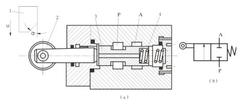
Figure 5.18 Two-position two-way motorized directional valve
1—stop iron; 2—roller; 3—spool; 4—spring
5.3.2.3 Solenoid-actuated DirecTIonal Valve
The electromagnetic directional valve uses the suction force of the electromagnet to push the valve core to change the working position of the valve. Because it can be controlled with the help of signals from the Button Switch, Journey Switch, Limit Switch, Pressure Switch, etc., it is easy to operate and easy to automate, so it is applied widely.
(1) Working principle
There are many varieties and specifications of electromagnetic directional valve, but the working principle is basically the same. The electromagnetic directional valve with the function of the three-position four-way O-type spool valve shown in Figure 5.19 is taken as an example for description.
In Figure 5.19, there are three annular undercut grooves in the valve body 1, with the oil inlet chamber P in the middle, and working oil chambers A and B adjacent to it. There are also two oil return chambers T connected to each other at both ends. Spring seat 3, return spring 4 and push rod 5 are respectively installed at both ends of the valve core, and an electromagnet is installed at each end of the valve body.
When both ends of the electromagnet are de-energized [see Figure 5.19 (a)], the spool is in the middle position. At this time, the oil chambers of P, A, B, and T are not in communication with each other; when the left end electromagnet is energized [see Figure 5.19 (b)], the electromagnet attracts and pushes the spool to move to the right, making P and B communicate , A and T are connected. When the power is turned off, the force of the return spring at the right end can return the spool to the middle position and restore the original four oil chambers to be closed to each other; when the right end electromagnet is energized [see Figure 5.19 (c)], its armature will Pushing the spool to the left by the push rod, P and A communicate, and B and T communicate. The solenoid is de-energized and the spool returns to the middle position under the action of the left spring.
(2) DC electromagnet and AC electromagnet
There are three types of solenoids for valves according to different power sources:
① Alternating current solenoid (AlternaTIng-current Solenoid). The operating voltage of the AC solenoid for valves is generally AC 220V, and the electrical circuit configuration is simple. The AC electromagnet has a large starting force and a short commutation time. However, the commutation impact is large, and the temperature rises during operation (so the outer shell is provided with radiating ribs); when the valve core is stuck, the electromagnet is easy to burn out due to excessive current, and the reliability is poor, so the switching frequency must not exceed 30 times / Minute; shorter life.
② DC electromagnet (DirecTIng-current Solenoid). DC electromagnets generally use 24V DC voltage, so a dedicated DC power supply is required. The advantage is that it will not burn out due to the iron core jamming (so there is no radiating rib on the cylindrical shell), the volume is small, the operation is reliable, the switching frequency is allowed to be 120 times per minute, the commutation impact is small, and the service life is long . But the starting power is smaller than the AC electromagnet.
③ This integral electromagnet. This integer type refers to the AC rectifier type. This electromagnet itself has a half-wave rectifier (Half-wave Rectifier), which can directly use AC power while having the structure and characteristics of DC electromagnet.
(3) Dry-type, oil-immersed, wet-type electromagnet
Whether it is DC electromagnet or AC electromagnetic, it can be made into dry type, oil immersed type and wet type.
① Dry Solenoid. The coil, iron core and yoke of the dry electromagnet are in the air and do not come into contact with oil. When the electromagnet is connected with the valve, there is a seal ring on the outer periphery of the push rod. Since the oil return may penetrate into the centering spring cavity, the oil return pressure of the valve cannot be too high. This type of electromagnet is equipped with a manual push rod. Once the electromagnet fails, the valve core can be manually replaced. This type of electromagnet is a form commonly used in simple hydraulic systems.
②Oil-immersed Solenoid. The coil and iron core of the oil-immersed electromagnet are immersed in the pressureless oil. The push rod and armature end are equipped with sealing rings. Oil can help the coil to dissipate heat, and can improve the lubrication condition of the push rod, so the service life is much longer than that of the dry electromagnet. Because of the multiple seals, this electromagnet has poor sensitivity and high cost.
③Wetted Solenoid. Wet electromagnets are also called pressure-resistant electromagnets. It is different from oil-immersed electromagnets in that there is no sealing ring at the push rod. Both the coil and the armature are immersed in the pressurized oil, so the heat dissipation is good and the friction is small. It also reduces the shock and noise during switching due to the damping effect of the oil. Therefore, the wet electromagnet has the advantages of low sound absorption, long life and low temperature rise. It is the most widely used electromagnet. Some people call both oil-immersed electromagnets and pressure-resistant electromagnets wet electromagnets.
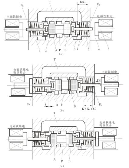
Figure 5.19 Working principle diagram of solenoid directional valve
1- Valve body; 2- Valve core; 3- Spring seat; 4- Spring; 5- Push rod; 6- Iron core; 7- Armature.
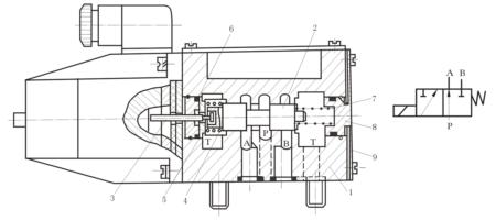
Figure 5.20 AC two-position three-way solenoid directional valve
1—Body; 2—Spool; 3—Push rod; 4, 7—Spring; 5, 8—Spring seat; 6—O ring; 9—Back cover.
(4) Typical Structure for Solenoid-actuated Directional Valve
Figure 5.20 shows an AC two-position three-way electromagnetic directional valve. When the electromagnet is de-energized, the valve core 2 is pushed to the left end by the spring 7 and P and A are connected; when the electromagnet is energized, the iron core pushes the valve core 2 to the right end through the push rod 3, so that P and B are connected.
Figure 5.21 is a DC wet three-position four-way electromagnetic directional valve. When the electromagnets on both sides are not energized, the spool 2 is in the neutral position under the action of the centering springs 4 on both sides, and the P, T, A, and B ports are not connected to each other; 2 Push to the left end, P and A pass, B and T pass, when the left electromagnet is energized, P and B pass, A and T pass.
It must be pointed out that due to the limited suction power of the electromagnet (120N), the electromagnetic directional valve is only suitable for occasions where the flow rate is not too large. When the flow is large, hydraulic or electro-hydraulic control is required.

Figure 5.22 Spring centered three-position four-way Hydraulic Directional Valve
5.3.2.4 Hydraulic Pressure-actuated Directional Valve
The hydraulic directional valve is a directional valve that uses control pressure oil to change the position of the spool. For the three-position valve, according to the centering form of the valve core, it is divided into two types: spring-centered and hydraulic centered. Figure 5.22 (a) shows a spring-centered three-position four-way hydraulic directional valve. The two ends of the valve core are connected to the control ports K1 and K2, respectively. When K1 passes pressure oil, the spool moves to the right, P and A pass, B and T pass; when K2 passes pressure oil, the spool moves to the left, P and B pass, A and T pass; when K1 and K2 are not connected When the oil is pressed, the spool is in the neutral position under the action of the centering springs at both ends. When the directional smoothness of the hydraulic spool is required to be high, a damping adjuster (Damping Adjuster) should also be installed in the K1 and K2 control oil circuits at both ends of the spool [see Figure 5.22 (c)]. The damping regulator consists of a One-way Valve and a throttle valve in parallel. The one-way valve is used to ensure the smooth flow of oil into the end face of the spool valve, and the throttle valve is used to restrict the return oil of the spool valve end face and adjust the size of the throttle valve You can adjust the spool action time.
5.3.2.5 Electro-hydraulic Directional Valve
Electro-hydraulic directional valve is a combination of electromagnetic directional valve and hydraulic directional valve. Among them, the electromagnetic directional valve plays a pilot role, controlling the action of the hydraulic directional valve, changing the working position of the hydraulic directional valve; the hydraulic directional valve is used as the main valve to control the actuator in the hydraulic system.
Due to the hydraulic pressure drive, the size of the main spool can be made very large, allowing a large flow through. Therefore, the electro-hydraulic directional valve is mainly used in hydraulic systems whose flow rate exceeds the rated flow rate of the electromagnetic directional valve, so that a larger flow rate can be controlled with a smaller electromagnet. The electrohydraulic directional valve is used in the same way as the electromagnetic directional valve.
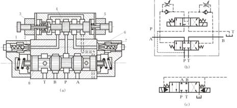
Figure 5.23 Spring-centered electrohydraulic directional valve with external control and external oil return
(a) Structural drawing; (b) Symbol; (c) Simplified symbol (b)
The electro-hydraulic directional valve has two types: spring centering and hydraulic centering. If classified according to control pressure oil and its oil return method, there are four types: external control and external oil return; external control and internal oil return; internal control and external oil return; internal control and internal oil return.
Figure 5.23 is the structure diagram and graphical symbols of the spring-centered three-position four-position electro-hydraulic directional valve (external control, external oil return).

June 27, 2023

August 01, 2024

August 01, 2024
A hydraulic diverter valve is a crucial component in hydraulic systems, allowing for the control and redirection of fluid flow. These valves are designed to handle high pressures and ensure smooth...
A leading manufacturer of hydraulic components is facing increasing demand for a specialized monoblock valve designed for use in log splitters. With competitors entering the market, the company must...
Hydraulic pump parts are essential components of hydraulic systems, used in various industries such as construction, agriculture, and manufacturing. These parts include pistons, cylinders, valves,...
A hydraulic dump truck power pack is a vital component that provides the necessary power to operate the hydraulic system of dump trucks. It consists of a hydraulic pump, reservoir, control valves,...
Email to this supplier
June 27, 2023
August 01, 2024
August 01, 2024
Privacy statement: Your privacy is very important to Us. Our company promises not to disclose your personal information to any external company with out your explicit permission.
Fill in more information so that we can get in touch with you faster
Privacy statement: Your privacy is very important to Us. Our company promises not to disclose your personal information to any external company with out your explicit permission.